If you’ve ever called a grinding parts supplier for a custom quote, you already know that the material of the part you need isn’t just a detail—it’s the backbone of every decision we make in our workshop. Last week, a client reached out for a set of precision gears made from 4140 alloy steel, and another followed up immediately with a request for thin-walled brackets from 6061-T6 aluminum. Both wanted tight tolerances, no surface defects, and fast turnaround. But if we’d used the same grinding parameters for both, we would have delivered scrap instead of parts that fit. That’s why adjusting grinding parameters to match the part material isn’t just a best practice—it’s non-negotiable for anyone in the grinding parts business. Over 12 years on the floor, I’ve seen more good parts ruined by ignoring this rule than by any other mistake, and today I want to walk through how we do it, from the shop floor to the final inspection. Grinding Parts

Let’s start with the basics: what even are grinding parameters? When I talk about them, I’m not just talking about how fast the wheel spins. They include wheel type, grit size, hardness, bond material, feed rate, grinding depth, coolant flow, and even spindle speed. Each of these variables interacts with the material you’re cutting, and choosing the wrong combination can cause everything from thermal burn on steel to built-up edge on aluminum, or even wheel loading that clogs your abrasive and makes the part rough. The goal is always material removal rate (MRR) paired with surface finish and dimensional accuracy, but the priority shifts entirely based on what you’re working with.
First, let’s break down the most common materials we grind in our shop, and how we adjust parameters for each. I’ll use examples from actual jobs we’ve done to make this concrete.
Alloy steels like 4140, 4340, and tool steels are the backbone of the industrial parts we supply. They’re strong, wear-resistant, but prone to thermal damage. Last year, we had a job for a set of high-performance shafts made from hardened 4140. The first run we tried using a standard aluminum oxide wheel (the workhorse for steel) at a grinding depth of 0.005 inches per pass, a feed rate of 50 inches per minute (IPM), and straight synthetic coolant. The parts came out with a dull gray tinge on the surfaces—thermal burn, which makes the steel brittle and can lead to failure in use. That’s when we adjusted. First, we swapped to a softer-grade aluminum oxide wheel (grade J instead of grade K). Hard wheels act like a knife that can’t sharpen itself when it gets loaded with steel chips; softer wheels release abrasive grains faster, so they self-dress and cut cooler. Next, we cut the grinding depth per pass by 40% to 0.003 inches, and dropped the feed rate to 35 IPM. Slower feed means each abrasive grain removes less material per revolution, reducing the heat generated at the cutting interface. We also switched to a semi-synthetic coolant with high sulfur content—sulfur acts as a lubricant for steel, reducing friction. The result? No burn, the parts hit their ±0.0002 inch tolerance, and surface finish was 16 Ra, which met the client’s requirements. For tool steels like D2, which are even harder, we go even slower: depth per pass drops to 0.0015 inches, and we use a ceramic aluminum oxide wheel instead of standard alumina. Ceramic grains are sharper and last longer when cutting hard, abrasive tool steel, so we don’t have to re-dress the wheel as often, and the process stays cooler.
Next up, aluminum alloys, like 6061, 7075, and cast aluminum. These are tricky because they’re soft, ductile, and their chips fuse easily to the grinding wheel—called built-up edge (BUE). BUE doesn’t just scratch the part; it makes the wheel uneven, leading to dimensional errors. A client needed thin-walled brackets from 6061-T6 a few months back, and on the first test piece, we used an aluminum oxide wheel and ran into immediate BUE. The wheel looked like it had plastic stuck to it, and the bracket walls were out of flatness by 0.008 inches (way too much for their ±0.001 inch requirement). So we adjusted. First, we swapped to a silicon carbide (SiC) wheel. SiC is harder than aluminum oxide and more chemically compatible with non-ferrous metals, so it doesn’t load as easily. We also used a coarse grit size—46 grit instead of 60. Coarser grains have more space between them, so aluminum chips can get ejected instead of getting stuck in the wheel. We increased the grinding depth per pass to 0.004 inches (aluminum is softer, so we can remove more material without burning) and boosted the feed rate to 70 IPM. Faster feed means the aluminum chips are sheared off before they have time to fuse to the wheel. We also used a high-pressure, high-flow coolant system—150 PSI, 10 gallons per minute—with a detergent additive to flush away any loose chips before they can cause BUE. The test bracket came out perfect, and the production run went off without a hitch. For cast aluminum, which has silicon particles that are abrasive, we switch to a diamond wheel with a metal bond. Metal bonds hold diamond grains tight, so the abrasive particles don’t fracture or pull out as quickly when cutting through hard silicon, and we get consistent cuts without loading.
Then there’s stainless steel, like 304, 316, and 17-4 PH. Stainless is a big one for medical, food, and aerospace parts, and it’s both ductile and prone to work hardening. Work hardening happens when the surface of the steel gets cold worked during grinding, making it harder than the base material and leading to excessive tool wear or dimensional instability. We had a job for 17-4 PH valve stems last quarter that called for a 20 Ra surface finish and tight roundness. First, we tried a standard alumina wheel at a moderate feed rate, and after the first pass, we noticed the surface was starting to work harden—we could see faint lines from the deformed material. So we adjusted two key parameters: first, we used a ground alumina wheel with a high porosity. Porous wheels have space to hold chips and coolant, so they don’t get clogged with the ductile stainless chips. Second, we increased the feed rate to 60 IPM. Faster feed means the material is removed before it has a chance to work harden. We also used a coolant with a rust inhibitor and lubricity additive—stainless is prone to rust, and good lubrication reduces friction that causes work hardening. For 304 stainless, which is more ductile than 17-4, we go even higher feed rates, up to 80 IPM, and use a softer grade wheel to prevent loading.
Now, it’s not just about wheel type and feed rate—there are other parameters that make a huge difference, especially for hard or exotic materials. Take titanium, like Ti-6Al-4V, which is widely used in aerospace and medical implants. Titanium is strong, lightweight, but has low thermal conductivity, so all the heat generated during grinding stays at the cutting edge, leading to thermal damage and wheel wear. For a set of titanium bone plates we supplied last year, we used a cubic boron nitride (CBN) wheel. CBN is second only to diamond in hardness, and it holds its shape much better than alumina when cutting titanium. We ran at a very low grinding depth per pass—0.001 inches, max—and a high spindle speed, 3600 RPM. High spindle speed means each abrasive grain is cutting faster, so the material is removed in tiny, discrete chips instead of being dragged and deformed, which reduces heat. We also used a cryogenic coolant system, which delivers liquid nitrogen directly to the cutting zone, keeping temperatures so low that we eliminated thermal burn entirely. The plates passed all fatigue and surface integrity tests, which was critical for the medical client.
I can’t stress enough that these aren’t one-size-fits-all rules. Every part has specific requirements, too—like if it’s thin-walled, which is more prone to deflection, or if it’s heat-treated, which changes its hardness. For a thin-walled aluminum component, for example, we reduce the grinding depth even more to prevent the part from bending under the grinding pressure, even if that means a few extra passes. For a heat-treated steel part, we make sure the wheel is properly dressed before starting, because heat-treated parts have a harder outer layer that can cause wheel glazing if the wheel isn’t sharp.
A common mistake I see newer grinding companies make is chasing high MRR at all costs, regardless of the material. Last year, a competitor quoted the same aluminum brackets we did, for a 10% lower price, by running at double our feed rate. But when the client got their parts, half of them had BUE scratches that made them unusable. They ended up throwing out the bad parts, re-quote with us, and said it was worth the extra 10% to get good parts the first time. That’s the value of adjusting parameters correctly: it’s not just about how fast you can cut, it’s about how many good parts come out the other end.
For our company, this is part of what makes us reliable. When a client sends us a print, we don’t just plug numbers into a machine—we pull on 12 years of experience, ask questions about the material’s grade, heat treatment, and the required surface finish and tolerance, and adjust every parameter to match. We track every job in a log: what wheel we used, what depth, feed rate, coolant, and what the results were. That log has become our most valuable tool, because it lets us refine our process every time, instead of repeating mistakes.
If you’re working on a grinding parts project and you’ve struggled with surface defects, dimensional errors, or inconsistent parts, the first question to ask your supplier is: what parameters did you use for this material? A good supplier will be able to walk you through those choices, explain why they worked, and adjust them if your requirements change. If they can’t, that’s a red flag.
At the end of the day, grinding is as much a craft as it is a science. The parameters aren’t just numbers on a screen—they’re the difference between a part that works for years and one that fails prematurely, between a batch that meets tolerance and one that gets scrapped. We’ve honed our process over thousands of jobs, and adjusting parameters to match the part material is the cornerstone of that work.
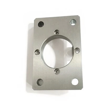
If you have a grinding project coming up, whether it’s steel gears, aluminum brackets, stainless valve parts, or titanium medical components, don’t leave the success of your part to guesswork. Reach out to our team, and we’ll walk through the material and your requirements to get you parts that meet your exact specs, on time, every time.
Special Purpose Machinery References:
- Malkin, S., & Guo, C. (2008). Grinding Technology: Theory and Applications of Machining with Abrasives. Industrial Press.
- Shaw, M. C. (1996). Principles of Abrasive Processing. Oxford University Press.
- Astakhov, V. P. (2006). Metallurgy of Machining. CRC Press.
- Bruyaka, A., et al. (2020). Effect of Grinding Parameters on Surface Integrity of 6061-T6 Aluminum Alloy. Journal of Manufacturing Processes.
Suzhou Huaquan Electromechanical Manufacturing Co., Ltd.
As one of the leading grinding parts manufacturers in China, we warmly welcome you to buy bulk customized grinding parts made in China here from our factory. If you have any enquiry about pricelist and free sample, please feel free to email us.
Address: No.7550 Mudong Road, Hengjing Town, Wuzhong District, Suzhou City, Jiangsu Province, China
E-mail: Huaquan2005@outlook.com
WebSite: https://www.huaquancnc.com/
